Creating LGR
On the LGR Creation form (model > 3D Grid > Modify Grid > Local Grid Refinement) you define an area inside the selected grid where you will apply grid refinement.
There are two definition types:
Box definition with which you specify the lateral and vertical start and end IJK cells.
Well definition with which you specify a volume inside the grid around a selected wellbore trajectory. You specify the lateral and vertical start and end IJK cells and a distance around the wellbore.
For both options, you also specify the number of refinement levels and the decay factors.
To create LGR
- Select the grid that you want to apply the local refinement to.
- Click Show to open the LGR Control View, which enables you to move vertically through the grid and display the successive k-layers.
-
To create one or more refinement definitions, right-click in the Select definition box and select one of the following options:
Add Box definition Constrain the refinement area to a rectangular box. A default box appears in the LGR Control View. To define the box parameters, see Step 4.
Add well definition Constrain the refinement area to a volume around a selected wellbore.
Delete definition Delete an existing definition. This does not remove an existing LGR from the grid.
When you check the LGR definition, the specified refinement is applied in the LGR computation.
- Select the appropriate LGR options (which depend on whether you chose a box or well definition.
You can also use the tools in the LGR Control View toolbar to define a box or well definition graphically.
The LGR Control View toolbar
To define the box definition graphically
- Click Box Edit Mode
 on the LGR Control View toolbar.
 - Click and drag the required box in the LGR Control View.
A box definition is created.
- In the LGR Creation form, define vertical extent, refinement level and decay factor as described in Box definition.
To define the well definition graphically
- Click Well Edit Mode
 on the LGR Control View toolbar.
 -
Click at a well.
A Well definition is created. By default an LGR is created around the first completion interval of the well.
- Define the Definition settings as described in Well definition.
Lateral range
Start I The first grid stack in the I direction that is included in the refinement box.
End I The last grid stack in the I direction that is included in the refinement box.
Start J The first grid stack in the J direction that is included in the refinement box.
End J The last grid stack in the J direction that is included in the refinement box.
Vertical extent
Top surface The shallowest k-layer of the refinement box. You can select a k-layer or a horizon, which automatically selects the k-layer of which it forms the top.
Base surface The deepest k-layer of the refinement box. You can select a k-layer or a horizon, which automatically selects the k-layer of which it forms the base.
Refinement level Set the number of refinement levels to apply. The maximum is 5.
If I, J or K is not checked, there is no refinement in that direction.
Decay factors The decay factor controls where the cell refinement starts from the outside to the inside. the decay factor ranges between 0 and 1. If the decay factor = 1, cell refinement starts at the outer edge of the box; if the decay factor = 0, cell refinement starts at the inner side of the box with only a minimum number of cells in the center being refined to the maximum refinement level. The maximum refinement level at which the decay factor can be applied depends on the available number of cells in combination with the size of the defined box, since not all levels will always fit.
The decay factor is a single value that is applied at all refinement levels.
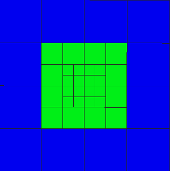
Example 1: refinement level = 2, decay factor = 0.5 click to enlarge
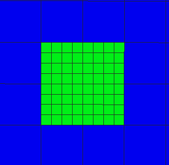
Example 2: refinement level = 2, decay factor = 1 click to enlarge
Wellbore Select the well around which you want to apply the Local Grid Refinement.
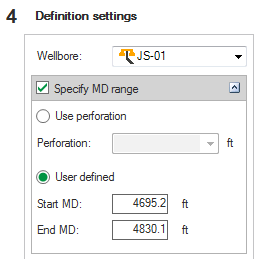
Well definition settings click to enlarge
Specify MD range Specify the well interval of the LGR as a perforation interval or as depth values.
Use perforation After selecting, choose a perforation interval from the drop-down list.
User defined Specify a Start MD and End MD depth value.
Specify MD range with layers Specify the well interval of the LGR as a number of successive k-layers.
Top surface The shallowest k-layer included in the refinement. You can select a k-layer or a horizon, which automatically selects the k-layer of which it forms the top.
Base surface The deepest k-layer included in the refinement. You can select a k-layer or a horizon, which automatically selects the k-layer of which it forms the base.
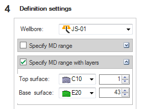
Specifying MD range with layers click to enlarge
Stop at fault Select if you want the grid refinement to stop when encountering a fault.
Refinement level Set the number of refinement levels to apply. The maximum is 10.
If I, J or K is not checked, there is no refinement in that direction.
Compute cells automatically Select if you want the required lateral extent of the refinement along the borehole to be automatically calculated taking the refinement level setting into account. The ‘Lateral extents’ and ‘Vertical extents’ options are not available.
Lateral extents If the Compute cells automatically option is not checked, you can set the lateral extent of the refinement as a number of Blocks or as a Distance.
Blocks Approximate number of cells around the wellbore included in the I and J direction. The actual number depends on cell sizes/dimensions/space in 3D grid.
Distance Distance around the wellbore in the I and J direction.
Vertical extents If the Compute cells automatically option is not selected, you can set the vertical extent of the refinement as a number of Blocks or as a Distance.
Blocks Approximate number of cells around the wellbore included in the K direction.
Distance Distance around the wellbore in the K direction.
Decay factors The decay factor controls where the cell refinement starts from the outside to the inside. If the decay factor = 1, cell refinement starts at the outer edge of the volume; if the decay factor = 0, only a minimum number of cells in the center are refined to the maximum refinement level. The maximum refinement level at which the decay factor can be applied depends on the available number of cells/size of the defined volume, since all levels do not always fit.
The decay factor is a single value that is applied at all refinement levels.
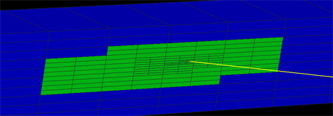
LGR well definition, 3D view, I slice click to enlarge
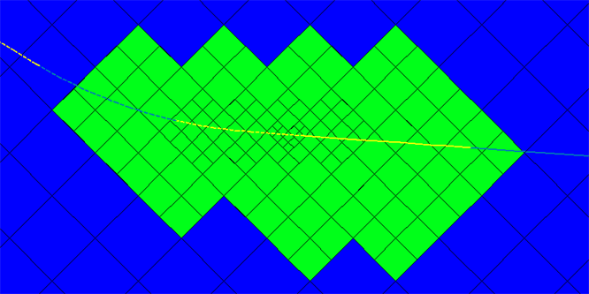
LGR well definition, LGR Control view, k-layer click to enlarge
- To display the cells affected by the refinement, click Compute Preview Property.
- To calculate the grid refinement at all refinement levels, click Compute.